Control Electronics & Pinout
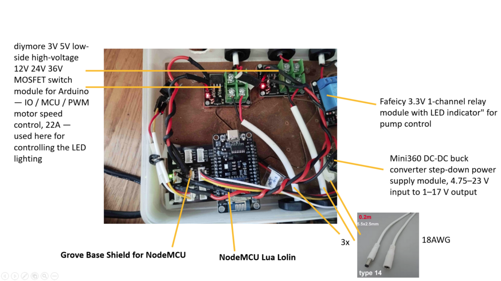
The wall is controlled by an ESP8266-based NodeMCU microcontroller running custom firmware. The controller handles pump scheduling, LED dimming, water level monitoring, and serves a web interface for configuration — all accessible over WiFi without physical access to the unit.
Microcontroller
The brain of the system is an ESP8266 NodeMCU (Wemos D1 Mini compatible pinout). All outputs operate at 3.3V logic level. The firmware is written in Arduino C++ and supports OTA (over-the-air) updates, meaning the software can be updated remotely without touching the hardware.
Pin Assignment
| Pin | GPIO | Function | Component |
|---|---|---|---|
| D3 | GPIO0 | Pump control | Fafeicy 3.3V 1-channel relay module |
| D5 | GPIO14 | LED channel 1 (PWM) | MOSFET module (diymore) |
| D6 | GPIO12 | LED channel 2 (PWM) | MOSFET module (diymore) |
| D1 | GPIO5 | Ultrasonic TRIG | AJ-SR04M water level sensor |
| D2 | GPIO4 | Ultrasonic ECHO | AJ-SR04M water level sensor |
| D4 | GPIO2 | Buzzer | KY-006 passive buzzer |
| A0 | ADC | Reserved | Moisture sensor (future use) |
Power Distribution
The system uses three separate DC power supplies. Each of the two LED strips runs on its own dedicated 24V supply — the supplies that came with the strips — with each strip switched independently via its own MOSFET module. Keeping the supplies separate avoids interference between channels and simplifies fault diagnosis. The pump and the Mini360 DC-DC buck converter share a single 12V supply. The buck converter steps the 12V down to 3.3V, fed directly into the VIN pin of the NodeMCU, bypassing the onboard regulator entirely.
Initial attempts to power the NodeMCU via the 5V VIN pin resulted in insufficient current delivery to the MOSFET modules — the LEDs glowed faintly rather than switching properly. Using the buck converter resolved this.
An important lesson from the build: wire gauge matters significantly at low voltages. Thin signal-grade wiring caused visible LED flickering under load. All power-carrying connections were therefore rebuilt using AWG 18 wire. The Grove connector carrier cables were assembled by hand using AWG 18 cores rather than standard thin Grove cable stock — this eliminated the flickering significantly.
Pump Control
The pump is switched via a diymore MOSFET module which bridges the 3.3V logic output of the ESP8266 to the 12V load side. The firmware supports three operating modes: manual on/off, interval-based automatic watering with configurable hours/minutes/seconds, and schedule-based watering with up to 8 daily trigger times. A pre-wetting mode delivers short bursts before the main watering cycle to counter hydrophobic fleece behaviour after extended dry periods — essential after the wall has been dry for more than a few hours.
LED Control
Two independent LED channels allow the light output to be split or staged across the wall. Both channels support PWM dimming via dedicated diymore MOSFET modules. The firmware implements a full daily light schedule with configurable ramp-up and ramp-down times, peak brightness windows, and a hard maximum PWM cap of 40%. The 3V–5V logic to 12V–24V switching capability of the MOSFET modules makes them well suited for driving LED strips directly from microcontroller pins.
Water Level Monitoring
A first attempt at water level monitoring used an AJ-SR04M ultrasonic sensor mounted in the tank lid. In practice, the sensor proved unsuitable for this setup: operated at 3.3V, its blind zone of approximately 20 cm made it unable to measure above roughly 40% fill level in the 34 cm tall tank.
The replacement will be a VL53L0X time-of-flight laser sensor. It offers millimetre resolution, no relevant blind zone, and runs natively at 3.3V via I2C – fitting directly into the existing sensor mounting hole in the tank lid with a PG13.5 adapter. The main uncertainty is whether the clear brown iron-chelate nutrient solution reflects the 940nm laser reliably at the water surface. A floating ping-pong ball in a guide tube is planned as a fallback reflector if direct surface measurement proves unreliable. The firmware calibration and daily logging logic remains unchanged.
Connectivity & Remote Management
The controller connects to the local WiFi network and exposes a web interface on port 80. All settings — watering schedules, LED timing, pre-wetting parameters — are configurable through the browser interface without touching the hardware. Firmware updates are delivered over-the-air (OTA) via a dedicated update endpoint. For a wall mounted in a hard-to-reach position, OTA capability is not a convenience feature — it is a necessity.
Components Used
| Component | Function |
|---|---|
| ESP8266 NodeMCU | Main controller |
| diymore MOSFET module 3V/5V → 12V/24V, 22A | Pump & LED switching |
| Fafeicy 3.3V 1-channel relay module with LED | Pump control (alternative) |
| Mini360 DC-DC buck converter 4.75–23V → 1–17V | 12V to 3.3V for NodeMCU |
| VL53L0X time-of-flight laser sensor | Water level measurement |
| KY-006 passive buzzer | Acoustic alerts |
| Grove connector carrier | Modular wiring |
| AWG 18 wire (custom Grove cables) | Power distribution — critical for stable LED operation |
Greenwall Control — Custom Firmware for Automated Living Walls
This firmware runs on an ESP8266/ESP32 microcontroller and manages all core functions of an automated vertical green wall: irrigation, LED grow lighting, and water tank monitoring — entirely self-contained, accessible via a local web interface over WiFi.
The irrigation system supports both interval-based and schedule-based watering cycles. A dedicated pre-wetting mode addresses the hydrophobic behaviour of dry fleece pockets by running short water bursts with absorption pauses before the main cycle begins — preventing runoff and ensuring even substrate saturation.
LED lighting follows a fully configurable daily schedule with smooth fade transitions between dim and full brightness phases, simulating natural light conditions for the plant community.
Water consumption is tracked via ansensor with a multi-point calibration system. All settings are stored persistently on-device and the firmware supports over-the-air (OTA) updates, so the controller never needs to be physically accessed after installation.
The interactive demo below reflects the actual web interface running on the device.